DOWNLOAD PDF

Get valuable resources straight to your inbox - sent out once per month
Subscribe
We value your privacy
Introduction
Automotive power systems operate under exceptionally harsh conditions. In particular, the car battery must handle numerous loads, and it can be challenging to determine the state of these loads simultaneously. Designers must consider the possible impact of the various pulses generated by the power line when these loads are under different operating conditions and potential fault states.
This is Part I of a two-part series describing how to design a reverse polarity protection circuit. In this article, we will introduce the various pulses on automotive power lines. Then we will discuss the common types of reverse polarity protection circuits, with a focus on a P-channel MOSFET circuit. Part II will discuss a reverse polarity protection circuit design using an N-channel MOSFET and driver IC.
Pulse Interferences
Figure 1 shows the various types of pulses that may appear on the power line in different application scenarios. For example, if the high-power load suddenly turns off, then the battery voltage can overshoot; if the high-power load suddenly starts up, then the battery voltage drops. When the inductive wiring harness is suddenly loosened, the load has a negative voltage pulse. Meanwhile the AC ripple is superimposed on the battery when the generator operates. When using jumper wires, the backup battery may be applied incorrectly, which causes reverse polarity. This reverse polarity can remain for a significant period of time.
Figure 1: Types of Pulses in Different Application Scenarios
To handle the various pulse interferences that may exist on these automotive power lines, industry associations and major vehicle manufacturers have developed relevant test standards to simulate power line transient pulses. These standards include the ISO 7637-2 and ISO 16750-2, as well as the test standards for Mercedes-Benz and Volkswagen. As the most front-end circuit of the module, the reverse polarity protection circuit must also meet industry test standards.
Related Content
- VIDEO MPSafe™ Automotive Functional Safety Introducing our ISO 26262 compliant functional safety product development process
- ARTICLE Power Supply Design for Car Infotainment Discover the requirements and advantages of primary power supplies
- LANDING PAGE EMC Testing Labs EMC testing facilities
- ARTICLE A Brief Primer on MPSafeTM MPS’s advanced process for automotive functional safety
Reverse Polarity Protection Circuits
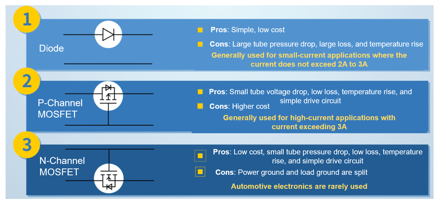
There are three basic types of reverse polarity protection circuits, described below.
Series Schottky Diode
This circuit is typically used for low-current applications between 2A and 3A. Advantages include simplicity and lower cost, but there is greater power loss.
P-Channel MOSFET on the High Side
For applications with currents exceeding 3A, a P-channel MOSFET can be placed on the high side. This driving circuit is relatively simple, though it is more expensive due to the P-channel MOSFET.
When the power supply is connected positively, the P-channel MOSFET is open. The channel voltage experiences a small drop, then the temperature rises and the overall power loss is reduced.
When the power supply is connected in the reverse direction, the P-channel MOSFET is closed, and the parasitic body diode accomplishes the reverse polarity protection function.
N-Channel MOSFET on the Low Side
Another circuit requires placing an N-channel MOSFET on the low side. The simplified gate drive circuit uses a cost-effective N-channel MOSFET. This circuit functions similarly to a P-channel MOSFET that has been placed on the high side; however, the reverse polarity protection structure of this system means that the power supply ground and load ground are separated. This structure is rarely used when designing electronic automotive products.
Figure 2 shows a summary of these reverse polarity protection circuits.
Figure 2: Types of Reverse Polarity Protection Circuits
This article will focus on the P-channel MOSFET reverse polarity protection circuit.
P-Channel MOSFET
Most traditional reverse polarity protection circuits use a P-channel MOSFET, where the P-channel MOSFET’s gate is connected to ground. If the input terminal is connected to the forward voltage, then the current flows through the P-channel MOSFET’s body diode to the load terminal. If the forward voltage exceeds the P-channel MOSFET’s voltage threshold, then the channel turns on. This reduces the P-channel MOSFET’s drain-to-source voltage (VDS), which reduces power loss. Generally, a voltage regulator is connected between the gate and source. This prevents the gate-to-source voltage (VGS) from experiencing an over-voltage condition, and it also protects the P-channel MOSFET from breakdowns when the input power fluctuates.
The basic P-channel MOSFET reverse polarity protection circuit has two disadvantages: a large system standby current and backflow current. These are described in greater detail below.
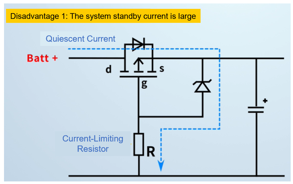
Large System Standby Current
When a P-channel MOSFET is used in a reverse polarity protection circuit, there is leakage current around VGS and the protection circuit (which consists of a Zener diode and a current-limiting resistor). Thus, the current-limiting resistor (R) affects the overall standby power consumption.
R should not be too large. The ordinary Zener diode is at the mA level. If the current-limiting resistance is too large, the Zener diode cannot reliably turn on, and its clamping performance is significantly reduced. This leads to an over-voltage risk on VGS. On the other hand, a larger R corresponds with a smaller P-channel MOSFET drive current, which results in slower opening/closing processes. If the input voltage (VIN) fluctuates, then the P-channel MOSFET may operate in the linear region (in which the MOSFET is not fully turned on) for a long time. The resulting higher resistance can lead to overheating.
Figure 3 shows the standby current in the traditional P-channel MOSFET reverse polarity protection circuit.
Figure 3: Standby Current in Traditional P-Channel MOSFET Reverse Polarity Protection Circuit
Backflow Current
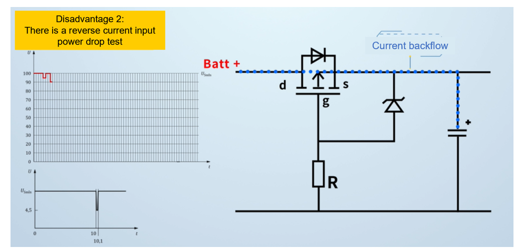
While performing an input power supply drop test for ISO 16750, the P-channel MOSFET stays open while VIN drops. In this situation, the system capacitor’s voltage reverses the power supply, which can result in system power failure and trigger an interrupt function. During the superimposed AC input voltage test, current backflow occurs since the P-channel MOSFET is completely open. This can force the electrolytic capacitor to repeatedly charge and discharge, which can cause overheating.
Figure 4 shows the input power supply drop test.
Figure 4: Input Power Supply Drop Test
Conclusion
In this article, we reviewed the traditional P-channel MOSFET reverse polarity protection circuit and its key disadvantages, including large system standby current and backflow current. Part II will discuss the advantages of designing a reverse polarity protection circuit design using an N-channel MOSFET and buck-boost driver IC.
_______________________
Did you find this interesting?Get valuable resources straight to your inbox - sent out once per month!
Technical Forum
Questions answered by MPS engineers in 24h
I want to know IC control method Hi everyone.I’m reviewing multi-phase controller+ DrMOS for efficiency increase and to cover heavy load current.Now I’m reviewing datasheet abou... AUTOMOTIVE SOLUTIONS Latest activity 5 days ago 2 Comments MPQ3367 input schottky diode question I have purchased an MPQ3367 EVB, and I have two questions that I would like to ask. The first question is, what is the function of the D3 Schottky dio... AUTOMOTIVE SOLUTIONS Latest activity 3 weeks ago 2 Comments GUI issue of mp6570 Hi,I bought an EVKT-MP6570 evaluation board but can’t find a suitable software to test this board. I spent an hour on the “eMotion Module Virtual... AUTOMOTIVE SOLUTIONS Latest activity 3 weeks ago 2 CommentsGet technical support


